Solved[December 2023] BCS41 - Fundamental of Comptuer Networks | IV SEM BCA IGNOU
Hey there! Welcome to KnowledgeKnot! Don't forget to share this with your friends and revisit often. Your support motivates us to create more content in the future. Thanks for being awesome!
Question 1(a). What is Frame Relay? Explain the advantages of Frame Relay over X.25 Network. (6 Marks)
Answer:
Frame Relay is a packet-switching technology used in computer networks to transmit data between devices. It operates at the data link layer of the OSI model, providing a connection-oriented service for efficient data transmission.
Advantages of Frame Relay over X.25 Network:
- Higher Data Transfer Rates: Frame Relay supports higher data transfer rates compared to X.25, making it suitable for faster communication needs.
- Reduced Overhead: Frame Relay has lower overhead than X.25, resulting in more efficient bandwidth utilization and reduced costs for transmitting data.
- Simplified Network Configuration: Frame Relay simplifies network configuration by eliminating the need for complex virtual circuit setup and maintenance, which is required in X.25 networks.
- Enhanced Scalability: Frame Relay offers better scalability, allowing for easier expansion of network capacity to accommodate growing data traffic compared to X.25.
- Improved Performance: Frame Relay provides better performance for real-time applications due to its reduced latency and more efficient data handling mechanisms compared to X.25.
- Cost-Effectiveness: Frame Relay is often more cost-effective than X.25, both in terms of initial setup costs and ongoing operational expenses, making it a preferred choice for many organizations.
Question 1(b). How are Hubs, Switches and Routers different from each other ? (6 Marks)
Answer:
Hubs, switches, and routers are networking devices that serve different functions in computer networks:
Hubs operate at the physical layer (Layer 1) of the OSI model.They are basic devices used to connect multiple network devices together, such as computers or printers, within a local area network (LAN). Hubs operate in half-duplex mode, meaning they can only transmit or receive data at any given time. When a hub receives data on one port, it broadcasts that data to all other ports, regardless of the intended destination, leading to increased network congestion and reduced performance.
Switches operate at the data link layer (Layer 2) of the OSI model. They are more intelligent than hubs and can forward data to specific devices within a network based on the Media Access Control (MAC) addresses of the devices. Switches create dedicated communication paths between devices, allowing for simultaneous data transmission between multiple devices without causing network congestion. They operate in full-duplex mode, enabling simultaneous data transmission and reception.
Routers operate at the network layer (Layer 3) of the OSI model. They are used to connect multiple networks together, such as connecting a local area network (LAN) to the internet. Routers make forwarding decisions based on IP addresses and routing tables, allowing them to determine the optimal path for data packets to reach their destination. They provide features such as network segmentation, packet filtering, and traffic management, which are essential for maintaining network security and optimizing performance. Routers operate in full-duplex mode and can support multiple communication interfaces, including Ethernet, Wi-Fi, and serial connections.
Question 1(c). Explain POP and IMAP. What are the advantages of IMAP over POP? (6 Marks)
Answer:
POP (Post Office Protocol) and IMAP (Internet Message Access Protocol) are both email protocols used for retrieving email messages from a mail server to a client device. Here's an explanation of each along with the advantages of IMAP over POP:
POP (Post Office Protocol):POP is an email protocol used for retrieving email messages from a mail server to a client device. In POP, emails are downloaded from the server to the client device, and typically, the emails are then deleted from the server. It operates in a "download and delete" mode, meaning once emails are downloaded to the client, they are removed from the server, and only stored locally on the client device. POP is simpler to configure and generally requires less server storage space compared to IMAP.
IMAP (Internet Message Access Protocol):IMAP is also an email protocol used for retrieving email messages from a mail server to a client device. Unlike POP, IMAP allows emails to be stored on the mail server even after they are downloaded to the client device. IMAP operates in a "keep on server" mode, meaning emails are kept on the server and can be accessed from multiple client devices. It offers more advanced features such as folder management, server-side search, and synchronization of email across multiple devices. IMAP is suitable for users who access their email from multiple devices or locations because it keeps emails synchronized across all devices.
Advantages of IMAP over POP:
- Email Synchronization: IMAP keeps emails synchronized across multiple devices, ensuring that changes made on one device are reflected on all other devices accessing the same email account.
- Server-Side Storage: IMAP allows emails to be stored on the server, providing access to emails from any device with an internet connection.
- Folder Management: IMAP supports folder management on the server, allowing users to organize emails into folders directly from their email client.
- Efficient Storage Usage: With IMAP, emails can be stored centrally on the server, reducing the storage space required on individual client devices.
- Server-Side Search: IMAP enables server-side search functionality, allowing users to quickly search for specific emails without having to download all emails to the client device.
- Accessibility: IMAP allows users to access their email accounts from anywhere with an internet connection, making it more suitable for users who need access to their emails from multiple locations or devices.
Question 1(d). Compare CSMA/CD and Ethernet Protocol. (6 Marks)
Answer:
CSMA/CD (Carrier Sense Multiple Access with Collision Detection) and Ethernet Protocol are both networking protocols used in LAN (Local Area Network) environments. Here's a comparison between the two:
CSMA/CD (Carrier Sense Multiple Access with Collision Detection):
→ CSMA/CD is a protocol used in Ethernet networks to control access to the network medium and manage collisions.
→ It operates by having devices listen for a carrier signal on the network before attempting to transmit data.
→ If a device detects that the network is idle, it can start transmitting data. However, if two devices attempt to transmit simultaneously and their signals collide, a collision is detected.
→ When a collision occurs, CSMA/CD employs a backoff algorithm to ensure that devices wait for a random amount of time before attempting to retransmit, reducing the likelihood of collisions reoccurring.
→ CSMA/CD is primarily used in older Ethernet networks, such as those based on 10BASE5 or 10BASE2 standards.
Ethernet Protocol:
→ Ethernet is a widely used networking protocol that defines the rules and specifications for data transmission over LANs.
→ It operates using packet-switching technology, where data is divided into packets and transmitted over the network.
→ Ethernet supports various transmission speeds and media types, including twisted pair cables, fiber optic cables, and wireless connections.
→ It uses MAC (Media Access Control) addresses to identify devices on the network and determine how data packets should be routed.
→ Ethernet frames include source and destination MAC addresses, as well as other control information such as frame type and frame check sequence (FCS) for error detection.
→ Ethernet is a foundational protocol in computer networking and is used in both wired and wireless LAN environments.
Comparison:
Relationship: CSMA/CD is a protocol used within the Ethernet standard for managing collisions, while Ethernet is the broader protocol that defines the rules for data transmission and network communication.
Functionality: CSMA/CD specifically deals with collision detection and resolution within Ethernet networks, ensuring efficient use of the network medium. Ethernet, on the other hand, encompasses a wider range of functionalities, including packet formatting, addressing, and media access control.
Evolution: CSMA/CD was more prevalent in older Ethernet networks, such as those based on 10BASE5 or 10BASE2 standards. However, with the evolution of Ethernet technology, newer Ethernet standards, such as Gigabit Ethernet and 10 Gigabit Ethernet, have largely replaced CSMA/CD with full-duplex communication and switched Ethernet networks.
Impact: While CSMA/CD was crucial for managing collisions in early Ethernet networks, its importance has diminished with advancements in Ethernet technology, leading to more efficient and reliable data transmission methods.
Question 1(e). How does circuit switching and packet switching differ? Give merit and demerit both. (6 Marks)
Answer:
In circuit switching, a dedicated communication path, known as a circuit, is established between two communicating parties for the duration of the communication session.The circuit remains reserved and exclusive for the duration of the communication, regardless of whether data is being transmitted or not.Circuit switching is commonly used in traditional telephone networks, where a physical connection is established between the caller and the receiver for the duration of the call.
Merit of circuit switching
Since a dedicated circuit is established for the communication session, circuit switching provides consistent and predictable performance, making it suitable for real-time applications such as voice and video calls.
Demerit of circuit switching
Circuits remain reserved even when data is not being transmitted, leading to inefficient use of network resources, especially in cases where communication sessions are short or sporadic.
In packet switching, data is transmitted in discrete units called packets, which are individually routed from the source to the destination over a shared network. Packets from multiple sources can travel along different paths and may arrive at the destination out of order, requiring reassembly before delivery. Packet switching is commonly used in modern computer networks, including the Internet, where data is broken down into packets for transmission.
Merit of packet switching
Packet switching allows for the dynamic allocation of network resources, as bandwidth is shared among multiple users and packets are only transmitted when data is available.
Demerit of packet switching
Variable Quality of Service: Since packets can travel along different paths and may experience delays or packet loss, packet switching can result in variable quality of service, especially for real-time applications sensitive to delay or jitter.
Question 1(f). Write the steps for Distance Vector Routing Algorithm. Show case the working of the algorithm with an example. ( 10 Marks)
Answer:
Steps in Distance Vector Routing Algorithm:
Step 1. Initialization:Each router initializes its routing table with the following information:
→ Distance to itself: 0
→ Distance to all other directly connected routers: Directly measured distances (or infinity if unreachable)
→ Next hop to reach directly connected routers: Neighbors' IP addresses
Step 2. Exchange Information: Routers periodically exchange routing information with their neighbors.
→ Each router sends its entire routing table to its neighbors.
→ Upon receiving routing tables from neighbors, routers update their own routing tables based on the received information.
Step 3. Update Distance Vectors: For each destination in the routing table
→ Calculate the distance to the destination via each neighbor by adding the distance to the neighbor and the distance from the neighbor to the destination.
→ Update the distance to the destination and the next hop in the routing table if a shorter path is found.
→ If no update is made, the router retains the current information.
Step 4. Iterative Process: Steps 2 and 3 are repeated iteratively until convergence is reached. Convergence occurs when no further changes are made to the routing tables, indicating that all routers have consistent routing information.
Example of Distance Vector Routing Algorithm:
Step 1. As we can see in the below diagram of a DVR Network. At initialization every router creates their local routing table by with the information of directly linked routers.
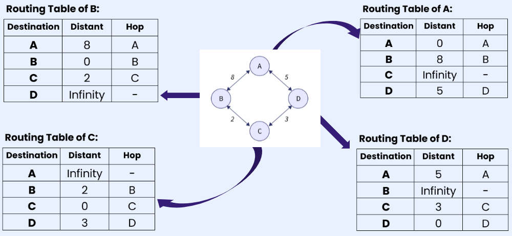
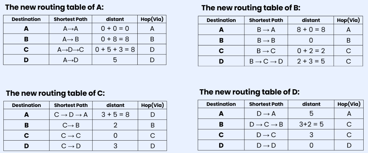
Step 2: After creating the separate local table, this information is shared with the neighboring node that has a direct link. Router A has direct connections with B and D, so A receives routing table information from B and D. The same applies to routers B, C, and D. Router B receives information from A and C. Router C receives information from B and D. Router D receives information from A and C. Each router searches for the minimum path to any other router and updates its routing table accordingly.
Question 2(a). Explain the working of 3-way handshake used in TCP using a suitable diagram. (10 Marks)
Answer:
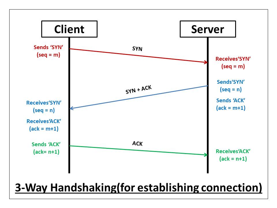
The 3-way handshake is a process used by TCP (Transmission Control Protocol) to establish a connection between a client and a server. It ensures that both the client and server are ready to send and receive data before actual data transmission begins. Here's how the 3-way handshake works:
Step 1: SYN (Synchronize):
→ The client sends a TCP segment to the server with the SYN (Synchronize) flag set to 1 and an initial sequence number (ISN) randomly chosen by the client.
→ This segment indicates the client's desire to establish a connection with the server and synchronizes the sequence numbers for data transmission.
→ After sending the SYN segment, the client enters the SYN_SENT state.
Step 2: SYN-ACK (Synchronize-Acknowledgment):
→ Upon receiving the SYN segment from the client, the server responds with a TCP segment with the SYN and ACK (Acknowledgment) flags set to 1.
→ The server also acknowledges the receipt of the client's SYN segment by including the client's initial sequence number (ISN) incremented by 1 in the acknowledgment field.
→ Additionally, the server generates its own initial sequence number (ISN) and includes it in the segment.
After sending the SYN-ACK segment, the server enters the SYN_RCVD state.
Step 3: ACK (Acknowledgment):
→ Finally, the client sends a TCP segment to the server with the ACK flag set to 1 and the acknowledgment number field set to the server's initial sequence number (ISN) incremented by 1.
→ This segment acknowledges the receipt of the server's SYN-ACK segment and confirms the establishment of the connection.
→ After sending the ACK segment, the client and server both enter the ESTABLISHED state, and data transmission can begin.
Question 2(b). What is Windowing? How are flow control and reliability achieved through windowing at transport layer? (10 Marks)
Answer:
Windowing is a technique used in the transport layer of computer networks, particularly in the Transmission Control Protocol (TCP), to manage the flow of data packets between a sender and a receiver. It helps in controlling the amount of data that can be sent before needing an acknowledgment from the receiver, thus ensuring efficient and reliable data transfer.
Flow control through windowing
Sliding Window Protocol:
→ The sliding window protocol is used to control the flow of data by adjusting the window size dynamically based on the network conditions and the receiver's ability to process data.
→ The sender maintains a window, which is a range of sequence numbers for packets that can be sent without waiting for an acknowledgment.
→ The receiver also maintains a window to manage the packets it can receive and process.
Adjustable Window Size:
→ The window size can be adjusted based on feedback from the receiver, often conveyed through acknowledgment packets.
→ If the receiver's buffer is filling up, it can reduce the window size to slow down the sender, preventing data overflow and packet loss.
→ if the receiver can handle more data, it can increase the window size, allowing the sender to transmit more packets before waiting for an acknowledgment.
Efficient Data Transmission:
→ Windowing allows the sender to continuously send a number of packets equal to the window size without waiting for individual acknowledgments, thus utilizing the available network bandwidth more efficiently.
→ This reduces idle time and improves overall data throughput. Reliability through Windowing:
Acknowledgments and Retransmissions:
→ Each packet sent within the window must be acknowledged by the receiver. If an acknowledgment is not received within a specified time (timeout), the sender assumes packet loss and retransmits the missing packet.
→ This mechanism ensures that all data packets are successfully delivered to the receiver, maintaining data integrity.
Cumulative Acknowledgments:
→ TCP uses cumulative acknowledgments, where an acknowledgment for a packet implicitly acknowledges the receipt of all previous packets.
→ This reduces the number of acknowledgment packets sent, improving efficiency and reducing overhead.
Sequence Numbers:
→ Each packet is assigned a unique sequence number, which helps the receiver to correctly order packets and detect any missing packets.
→ If packets arrive out of order, the receiver can use the sequence numbers to request retransmission of the missing packets, ensuring reliable delivery.
Flow Control Mechanism:
→ The receiver advertises its current window size (also known as the receive window) in each acknowledgment packet.
→ The sender adjusts its sending rate based on the advertised window size, preventing buffer overflow at the receiver and ensuring smooth data flow.
Question 3(a). List various connecting devices in a LAN. Explain the functioning of each. Also show the interconnectivity between devices with suitable diagram. (10 Marks)
Answer:
Various Connecting Devices in a LAN:
Hub: A hub is a simple networking device that operates at the physical layer (Layer 1) of the OSI model. It receives data packets from one device and broadcasts them to all other devices connected to the hub. Hubs are essentially multiport repeaters that amplify and forward incoming data to all connected devices without any intelligence to filter or manage traffic. However, they suffer from collisions and have limited bandwidth sharing capabilities.
Switch: A switch is a more intelligent networking device that operates at the data link layer (Layer 2) of the OSI model. It receives data packets from one device and forwards them only to the intended recipient based on the Media Access Control (MAC) address. Switches maintain a MAC address table to store the MAC addresses of connected devices and their corresponding switch ports. Unlike hubs, switches offer full-duplex communication, allowing simultaneous data transmission and reception, and they mitigate collisions by creating separate collision domains for each port.
Router: A router is a networking device that operates at the network layer (Layer 3) of the OSI model. It connects multiple networks together and forwards data packets between them based on IP addresses. Routers maintain routing tables to determine the best path for data packets to reach their destination network. They provide functionalities such as network segmentation, packet filtering, and traffic management, enhancing network security and optimizing performance.

Question 3(b). Briefly discuss the utility of CRC. Calculate CRC if the message is x7+x5+1 and generator polynomial is x3+1. (10 Marks)
Anwer:
Cyclic Redundancy Check (CRC) is a widely used error-detecting code that helps identify changes to raw data in digital networks and storage devices. Its utility includes:
- Error Detection: CRC is designed to detect accidental changes to raw data, ensuring data integrity during transmission or storage.
- Efficiency: It is computationally efficient, requiring simple binary arithmetic which can be performed quickly by hardware or software.
- Reliability: CRC can detect common errors such as single-bit errors, double-bit errors, burst errors, and even some types of more complex errors.
- Versatility: It can be used in various fields including networking (e.g., Ethernet frames), data storage (e.g., hard drives), and telecommunications.
Given that the message polynomial is x7+x5+1 and the generator polynomial is x3+1.
The highest degree of the polynomial is 3, so three zeros will be added to the message polynomial.
Now, let's write the message polynomial in binary form: 10100001000 and the generator polynomial in binary form: 1001.
Let's apply the long division:

The final remainder is 110.
So, the CRC for the message polynomial x7+x5+1 with the generator polynomial x3+1 is 110 in binary.
Question 4(a). Differentiate between Analog and Digital Modulation. Compare and contrast between ASK, PSK and FSK (digital modulation techniques). (10 Marks)
Answer:
Modulation Techniques in Communication Systems
Modulation is a method used in communication systems to encode information onto a carrier signal for transmission through a channel. There are two primary approaches: analog and digital modulation, each serving distinct purposes and possessing unique traits.
Analog Modulation - In analog modulation, the continuous characteristics of the carrier signal, such as amplitude, frequency, or phase, are adjusted in proportion to the analog signal being transmitted. This method is employed for transmitting analog signals like voice, music, and video. Examples include Amplitude Modulation (AM), Frequency Modulation (FM), and Phase Modulation (PM). However, analog modulation is susceptible to noise and interference, which can degrade communication quality and reliability.
Digital Modulation involves converting digital data into a digital signal, with discrete symbols or bits representing the information to be transmitted. This approach is used for transmitting digital signals such as data, text, and images. Examples include Amplitude Shift Keying (ASK), Phase Shift Keying (PSK), and Frequency Shift Keying (FSK). Digital modulation offers better resistance to noise and interference, thereby enabling more dependable communication compared to analog modulation.
Comparison of ASK, PSK, and FSK
Amplitude Shift Keying (ASK) - ASK alters the amplitude of the carrier signal to convey digital data. In ASK, two amplitudes of the carrier signal denote binary '1' or '0'. While ASK is straightforward to implement, it is sensitive to variations in amplitude and noise.
Phase Shift Keying (PSK) - : PSK modifies the phase of the carrier signal to represent digital data. Various phases of the carrier signal correspond to different symbols or bits. PSK is resilient against amplitude fluctuations but may be vulnerable to phase noise.
Frequency Shift Keying (FSK) : FSK adjusts the frequency of the carrier signal to convey digital data. Different frequencies of the carrier signal signify distinct symbols or bits. FSK is less affected by amplitude and phase variations but necessitates a wider bandwidth compared to ASK and PSK.
Question 4(b). What is MD5? Write step by step procudure for generating 128 bit MD5 digest. (10 Marks)
Answer:
MD5 is a cryptographic hash function algorithm that takes the message as input of any length and changes it into a fixed-length message of 16 bytes. MD5 algorithm stands for the message-digest algorithm. MD5 was developed as an improvement of MD4, with advanced security purposes. The output of MD5 (Digest size) is always 128 bits. MD5 was developed in 1991 by Ronald Rivest.
Use Of MD5 Algorithm:
→ It is used for file authentication.
→ In a web application, it is used for security purposes. e.g. Secure password of users etc.
→ Using this algorithm, We can store our password in 128 bits format.
MD5 algorithm follows the following steps
- Append Padding Bits: In the first step, we add padding bits in the original message in such a way that the total length of the message is 64 bits less than the exact multiple of 512. Length(original message + padding bits) = 512 * i – 64 where i = 1,2,3 . . .
- Append Length Bits: Append a 64-bit representation of the original message length (in bits) to the padded message. i.e. output of first step = 512 * n – 64 ,length bits = 64. After adding both we will get 512 * n i.e. the exact multiple of 512.
- Initialize Variables: Initialize four 32-bit variables (A, B, C, D) with fixed hexadecimal values (specified by the MD5 standard).
- Process Message in 16-Word Blocks: The message is processed in 512-bit blocks (16-word blocks), which is formed by dividing the message into chunks of 512 bits.
- Iterative Process: MD5 uses a series of four similar functions (F, G, H, I) in its iteration process, which operate on a 32-bit word. These functions perform bitwise operations, logical operations, and addition modulo 232.
- Update Variables: After each iteration, the four variables (A, B, C, D) are updated with the output of the functions in a specific order.
- Output: Once all the blocks are processed, the output is generated by concatenating the values of the four variables (A, B, C, D) in little-endian format.
Question 5(a). Differentiate between adaptive and non-adaptive routing. Explain the working of heirarichal routing using suitable topological structure and routing table. (10 Marks)
Answer:
Adaptive routing is a dynamic routing method where routes can change based on the current network conditions. It adapts to changes such as traffic load, network failures, or topology changes, leading to improved performance in terms of congestion management and fault tolerance. For example, if a particular route becomes congested, an adaptive routing algorithm might redirect traffic through a less congested path. Algorithms commonly used in adaptive routing include Distance Vector, Link State, OSPF (Open Shortest Path First), and AODV (Ad hoc On-Demand Distance Vector).
In contrast, non-adaptive routing, also known as static routing, uses fixed paths which do not change based on network conditions. Routes are predefined and remain constant regardless of the state of the network, providing simplicity and predictability in network performance. An example of non-adaptive routing is a predefined path between two nodes that does not change even if the network becomes congested. Algorithms used in non-adaptive routing include Shortest Path, Fixed Routing, and manually configured Routing Tables.
Hierarchical Routing:
Hierarchical routing is a method to manage routing in large networks by breaking them down into smaller, manageable regions or domains. This approach reduces the complexity and overhead associated with maintaining a large number of routes in extensive networks.
Consider a multi-level hierarchical network divided into three levels:
- Level 1 (Local Network): Small networks or subnets within a specific region.
- Level 2 (Regional Network): Aggregates multiple Level 1 networks.
- Level 3 (Core Network): Interconnects different regional networks.
Example Topology:

Working of Hierarchical Routing:
In intra-region routing (within Level 1), traffic between LA1 and LA2 is routed directly as they are in the same local network. In inter-region routing (between Levels 1 and 2), traffic from LA1 to LB1 is first routed to the Region A router, then forwarded to the Region B router, which finally sends it to LB1. In core network routing (Level 3), for traffic from LA1 to LC1, it first reaches the Region A router, which sends it to the core network router. The core network router forwards it to the Region C router, which then delivers it to LC1.
Hierarchical routing simplifies management by reducing the size of routing tables and limiting the scope of route information propagation. Each level of the hierarchy manages routes within its scope, while inter-region traffic is efficiently handled by higher levels in the hierarchy.
Question 5(b). Discuss the error control techniques used at data link layer. Also write the step by step procedure of Go-BACK-N ARQ Method. (10 Marks)
Error control techniques are essential at the data link layer to ensure reliable data transfer across a network. These techniques help detect and correct errors that may occur during transmission. The primary error control techniques used at the data link layer include:
- Error Detection: This technique involves identifying the presence of errors in the transmitted data. Common error detection methods are:
- Parity Check: Adds a parity bit to the data to make the number of 1s either even (even parity) or odd (odd parity). If the parity bit does not match the expected value, an error is detected.
- Cyclic Redundancy Check (CRC): Uses polynomial division to detect errors. The sender appends a CRC code to the data frame, and the receiver performs the same division. If the remainder is non-zero, an error is detected.
- Checksum: Similar to CRC, a checksum is calculated and appended to the data. The receiver calculates the checksum again and compares it to the received checksum to detect errors.
- Error Correction: This technique involves correcting errors detected in the transmitted data. Common error correction methods are:
- Automatic Repeat Request (ARQ): Combines error detection with retransmission requests. If an error is detected, the receiver requests the sender to retransmit the erroneous data.
- Forward Error Correction (FEC): Uses redundant data to correct errors without needing retransmission. Examples include Hamming code and Reed-Solomon code.
Go-Back-N ARQ Method:
Go-Back-N ARQ is an error control protocol that allows the sender to send multiple frames before needing an acknowledgment for the first frame, but requires retransmission of all frames from a lost or corrupted frame onwards. The step-by-step procedure of the Go-Back-N ARQ method is as follows:
- Initialization: Both sender and receiver maintain a window of sequence numbers. The sender's window allows sending up to N frames without waiting for an acknowledgment. The receiver's window expects frames in order and can store out-of-order frames temporarily.
- Transmission: The sender transmits frames continuously up to the window size N. Each frame is assigned a sequence number.
- Receiving and Acknowledgment:
- If the receiver correctly receives a frame, it sends an acknowledgment (ACK) back to the sender for that frame. The receiver then expects the next frame in sequence.
- If the receiver detects an error in a frame or if a frame is lost, it discards that frame and all subsequent frames. The receiver sends a negative acknowledgment (NAK) or no acknowledgment for the erroneous frame.
- Sliding Window: Upon receiving an ACK, the sender slides its window forward and sends new frames. For each ACK received, the sender advances its window to include the next unacknowledged frame.
- Retransmission: If the sender receives a NAK or times out waiting for an ACK, it retransmits the erroneous frame and all subsequent frames in the window. The sender continues this process until all frames are acknowledged correctly.
- Completion: The process continues until the sender has no more frames to send, and all frames have been acknowledged correctly by the receiver.
Go-Back-N ARQ ensures reliable data transmission by retransmitting frames from the point of error detection, albeit at the cost of potentially retransmitting multiple frames. This method balances simplicity and efficiency in handling errors at the data link layer.